
EN10327
Continuously hot-dip
coated strip and sheet
of low carbon steels for
cold forming —
Technical delivery
conditions
National foreword
This British Standard is the official English language version of
EN 10327:2004. It supersedes BS EN 10142:2000, and together with
BS EN 10326:2004, supersedes BS EN 10154:2002, BS EN 10214:1995 and
BS EN 10215:1995, which are withdrawn.
The UK participation in its preparation was entrusted to Technical Committee
ISE/10, Flat rolled steel products, which has the responsibility to:
— aid enquirers to understand the text;
— present to the responsible international/European committee any
enquiries on the interpretation, or proposals for change, and keep the
UK interests informed;
— monitor related international and European developments and
promulgate them in the UK.
A list of organizations represented on this committee can be obtained on
request to its secretary.
Cross-references
The British Standards which implement international or European
publications referred to in this document may be found in the BSI Catalogue
under the section entitled “International Standards Correspondence Index”, or
by using the “Search” facility of the BSI Electronic Catalogue or of
British Standards Online.
This publication does not purport to include all the necessary provisions of a
contract. Users are responsible for its correct application.
Compliance with a British Standard does not of itself confer immunity
from legal obligations.
Summary of pages
This document comprises a front cover, an inside front cover, the EN title page,
pages 2 to 23 and a back cover.
The BSI copyright notice displayed in this document indicates when the
document was last issued.
Continuously hot-dip coated strip and sheet of low carbon steels
for cold forming - Technical delivery conditions
Bandes et tфles en acier doux revкtues en continu par Kontinuierlich schmelztauchveredeltes Band und Blech aus
immersion а chaud pour formage а froid - Conditions weichen Stдhlen zum Kaltumformen - Technische
techniques de livraison Lieferbedingungen
This European Standard was approved by CEN on 23 April 2004.
CEN members are bound to comply with the CEN/CENELEC Internal Regulations which stipulate the conditions for giving this European
Standard the status of a national standard without any alteration. Up-to-date lists and bibliographical references concerning such national
standards may be obtained on application to the Central Secretariat or to any CEN member.
This European Standard exists in three official versions (English, French, German). A version in any other language made by translation
under the responsibility of a CEN member into its own language and notified to the Central Secretariat has the same status as the official
versions.
CEN members are the national standards bodies of Austria, Belgium, Cyprus, Czech Republic, Denmark, Estonia, Finland, France,
Germany, Greece, Hungary, Iceland, Ireland, Italy, Latvia, Lithuania, Luxembourg, Malta, Netherlands, Norway, Poland, Portugal, Slovakia,
Slovenia, Spain, Sweden, Switzerland and United Kingdom.
Foreword
This document (EN 10327:2004) has been prepared by Technical Committee ECISS/TC 27 “Surface coated flat
products – Qualities, dimensions, tolerances and specific tests”, the secretariat of which is held by DIN.
This European Standard shall be given the status of a national standard, either by publication of an identical text or
by endorsement, at the latest by January 2005, and conflicting national standards shall be withdrawn at the latest
by January 2005.
This European Standard supersedes EN 10142:2000 and, together with EN 10326, it also supersedes EN
10154:2002, EN 10214:1995 and EN 10215:1995.
This document includes a Bibliography.
According to the CEN/CENELEC Internal Regulations, the national standards organizations of the following
countries are bound to implement this European Standard: Austria, Belgium, Cyprus, Czech Republic, Denmark,
Estonia, Finland, France, Germany, Greece, Hungary, Iceland, Ireland, Italy, Latvia, Lithuania, Luxembourg, Malta,
Netherlands, Norway, Poland, Portugal, Slovakia, Slovenia, Spain, Sweden, Switzerland and United Kingdom.
1 Scope
1.1 This document specifies requirements for continuously hot-dip coated products made of low carbon steels for
cold forming coated with zinc (Z), zinc-iron alloy (ZF), zinc-aluminium alloy (ZA), aluminium-zinc alloy (AZ) and
aluminium-silicon alloy (AS) (see Table 1) with thicknesses of 0,35 mm to 3,0 mm unless otherwise agreed (see
1.2). The thickness is the final thickness of the delivered product after coating.
This document applies to strip of all widths and to sheets cut from it (≥ 600 mm width) and cut lengths
(< 600 mm width).
1.2 If agreed at the time of enquiry and order, this document may also be applied to continuously hot-dip coated
flat products in thicknesses > 3,0 mm. In this case the mechanical property, adhesion of coating and surface
condition requirements shall also be agreed at the time of enquiry and order.
1.3 The products covered by this document are mainly used where cold formability and corrosion resistance are
the most important factors. Corrosion resistance of the alloy is proportional to the coating thickness, hence to its
mass (see also 7.3.2).
1.4 This document is not applicable to:
• continuously hot-dip coated structural steel flat products (see EN 10326);
• electrolytically zinc coated cold rolled steel flat products (see EN 10152);
• continuously organic coated (coil coated) steel flat products (see EN 10169-1, ENV 10169-2 and
EN 10169-3);
• continuously hot-dip coated strip and sheet of steels with higher yield strength for cold forming (see EN 10292).
2 Normative references
The following referenced documents are indispensable for the application of this document. For dated references,
only the edition cited applies. For undated references, the latest edition of the referenced document (including any
amendments).
EN 10002-1, Metallic materials – Tensile testing – Part 1: Method of test at ambient temperature.
EN 10020:2000, Definition and classification of grades of steel.
EN 10021:1993, General technical delivery requirements for steel and steel products.
EN 10027-1, Designation systems for steels – Part 1: Steel names, principal symbols.
EN 10027-2, Designation systems for steels – Part 2: Numerical system.
EN 10079:1992, Definition of steel products.
EN 10143, Continuously hot-dip metal coated steel sheet and strip - Tolerances on dimensions and shape.
EN 10204:1991, Metallic products – Types of inspection documents.
ISO 10113, Metallic materials – Sheet and strip – Determination of plastic strain ratio.
ISO 10275, Metallic materials – Sheet and strip – Determination of tensile strain hardening exponent.
CR 10260, Designation systems for steel – Additional symbols.
3 Terms and definitions
For the purposes of this document, the terms and definitions given in EN 10020:2000, EN 10021:1993, EN
10079:1992 and EN 10204:1991 and the following apply.
NOTE 1 General guidelines for the protection of iron and steel can be found in EN ISO 14713.
NOTE 2 In the present cases, strip is continuously hot-dip coated in a bath the composition of which is given in 3.1 to 3.4.
3.1
hot-dip zinc coating (Z)
application of a zinc coating by immersing the prepared products in a molten bath containing a zinc content of at
least 99 % (see also 7.4.2)
3.2
hot-dip zinc-iron coating (ZF)
application of a zinc coating by immersing the prepared products in a molten bath containing a zinc content of at
least 99 % ; subsequent annealing produces an iron-zinc coating with an iron content of normally 8 % to 12 % (see
also 7.4.3)
3.3
hot-dip zinc-aluminium alloy coating (ZA)
application of a zinc-aluminium coating by immersing the prepared products in a molten bath which is composed of
zinc and approximately 5 % aluminium
3.4
hot-dip aluminium-zinc alloy coating (AZ)
application of an aluminium-zinc coating by immersing the prepared products in a molten bath which is composed
of 55 % aluminium, 1,6 % silicon and the balance zinc
3.5
hot-dip aluminium-silicon alloy coating (AS)
application of an aluminium-silicon coating by immersing the prepared products in a molten bath which is
composed of aluminium and 8 % to 11 % silicon
3.6 coating mass
total mass of coating including both surfaces of the product (expressed in grams per square metre)
4 Classification and designation
4.1 Classification
In accordance with EN 10020 the steel grades covered by this document are alloy quality steels. They are
classified in accordance with their increasing suitability for cold forming as follows (see Table 1):
DX51D: bending and profiling quality;
DX52D: drawing quality;
DX53D: deep drawing quality;
DX54D: special deep drawing quality;
DX55D: special deep drawing quality, (only +AS), heat resistance up to 800 °C;
DX56D: extra deep drawing quality;
DX57D: super deep drawing quality.
4.2 Designation
4.2.1 Steel names
For the steel grades covered by this document, the steel names as given in Table 1 are allocated in accordance
with EN 10027-1 and CR 10260.
4.2.3 Steel numbers
For the steel grades covered by this document, the steel numbers as given in Table 1 are allocated in accordance
with EN 10027-2.
5 Information to be supplied by the purchaser
5.1 Mandatory information
The following information shall be supplied by the purchaser at the time of enquiry and order:
a) quantity to be delivered;
b) type of product (strip, sheet, cut length);
c) number of the dimensional standard (EN 10143):
d) nominal dimensions and the tolerances on dimensions and shape and, if applicable, letters denoting relevant
special tolerances;
e) term "steel";
f) number of this document (EN 10327);
g) steel name or steel number and symbol for the type of hot-dip coating as given in Table 1;
h) number designating the nominal mass of coating (e.g. 275 = 275 g/mІ including both surfaces, see
Tables 3 to 6);
i) letter denoting the coating finish (N, M or R, see 7.3 and Tables 4 and 5);
j) letter denoting the surface quality (A, B or C, see 7.5);
k) letter denoting the surface treatment (C, O, CO, S, P or PO, see 7.6).
EXAMPLE 1 sheet, delivered with dimensional tolerances in accordance with EN 10143 with nominal thickness of 0,80
mm, ordered with special thickness tolerances (S), nominal width 1200 mm, ordered with special width tolerances (S), nominal
length 2500 mm, ordered with special flatness tolerances (FS), made of steel DX53D+ZF (1.0355+ZF) in accordance with EN
10327, coating mass 100 g/mІ (100), coating finish R, surface quality B, surface treatment oiled (O):
1 sheet EN 10143-0,80Sx1200Sx2500FS
steel EN 10327-DX53D+ZF100-R-B-O
or:
1 sheet EN 10143-0,80Sx1200Sx2500FS
steel EN 10327-1.0355+ZF100-R-B-O
5.2 Options
A number of options are specified in this document and listed below. lf the purchaser does not indicate his wish to
implement one of these options, the products shall be supplied in accordance with the basis specification of this
document (see 5.1).
a) delivery of products in thicknesses > 3 mm (see 1.2);
b) verification of the product analysis (see 7.1.2);
c) products supplied suitable for the manufacture of a specific part (see 7.2.2);
d) coating masses different from those of Tables 3 to 5 and/or special requirements for different coating masses
on each surface (see 7.3.2);
e) products with pronounced spangle (see 7.4.2.1 or 7.4.5);
f) special requirements for a maximum Al-Fe-Si alloy layer mass occuring during hot-dip aluminium-silicon
coating (see 7.4.6);
g) requirement for special applications on bright appearance for hot-dip aluminium-silicon coated products (type B
surface, see NOTE to 7.5.3);
h) type of S coating (see 7.6.5);
i) products supplied free from coil breaks (see 7.7);
j) products supplied free from stretcher strains when cold forming (see 7.8.2);
k) special requirements for a maximum or minimum value for the coating mass per product surface (see 7.9.2);
l) notification of which surface has been inspected (see 7.10.1);
m) testing for compliance with the requirements of this document (see 8.1.1 and 8.1.2);
n) supply of an inspection document and type of document (see 8.1.2);
o) marking desired by branding of the products (see 9.2);
p) requirement for packing (see Clause 10).
6 Manufacturing process
The processes used in steelmaking and manufacture of the products are left to the discretion of the manufacturer.
7 Requirements
7.1 Chemical composition
7.1.1 The chemical composition according to the cast analysis shall be as specified in Table 1.
7.1.2 If a product analysis is agreed at the time of enquiry and order, the permitted deviations from the cast
analysis given in Table 1 shall meet the requirements in Table 2.
7.2 Mechanical properties
7.2.1 The products shall be supplied on the basis of the mechanical property requirements in Table 1.
7.2.2 lf so agreed at the time of enquiry and order, products specified in Table 1, except those made of steel
grade DX51D, may be supplied with suitability for manufacturing a specific part. In this case the values given in
Table 1 do not apply. The reject tolerances arising when the material is processed shall not exceed a specific
proportion to be agreed at the time of enquiry and order.
7.2.3 If ordered in accordance with 7.2.1, the mechanical property values in Table 1 apply for the following
periods commencing from the date on which the products are made available, unless otherwise agreed at the time
of enquiry and order:
1 month for steel grades DX51 D, DX52D coated in accordance with Table 1;
6 months for steel grades DX53D, DX54D, DX55D, DX56D and DX57D coated in accordance with Table 1.
7.2.4 The tensile test values apply to transverse test pieces and are related to the test piece cross section
without coating.
Table 1 — Steel grades and mechanical properties (transverse test pieces)
 |
Table 2 — Permissible deviations of the product analysis from specified limits on cast analysis given in
| Element |
Specified limit of the cast analysis in Table 1 % by mass |
Permissible deviation of the product analysis % by mass |
|---|---|---|
| C | Si | 0,50 + 0,03 |
| Mn | 0,60 | + 0,10 |
| P | 0,10 | + 0,01 |
| S | 0,045 | + 0,005 |
| TI | 0,30 | + 0,01 |
7.3 Coatings
7.3.1 The products shall be supplied with coatings of zinc (Z), zinc-iron-alloy (ZF), zinc-aluminium-alloy (ZA),
aluminium-zinc-alloy (AZ) and aluminium-silicon-alloy (AS) are given in Tables 3 to 6.
7.3.2 The available coating masses are given in Table 3. Deviating coating masses and/or different coating
masses on each surface may be supplied if agreed at the time of enquiry and order.
Thicker coatings may limit the formability and weldability of the products. Therefore, the forming and weldability
requirements shall be taken into account when ordering the coating mass.
The two surfaces may have a different appearance as a result of the manufacturing process.
7.4 Coating finish (see Tables 4 to 6)
7.4.1 General
Depending on the coating conditions, crystals of different sizes and brightness arise. The quality of the coating is
not affected by this.
7.4.2 Zinc coated products (Z)
7.4.2.1 Normal finish (N)
The finish is obtained when the zinc coating is left to solidify normally. Either no spangle or zinc crystals of different
sizes and brightness appear depending on the galvanizing conditions. The quality of the coating is not affected by
this.
lf a pronounced spangle is desired, this shall be indicated specially at the time of enquiry and order.
7.4.2.2 Minimized spangle (M)
The finish is obtained by influencing the solidification process in a specific way. The surface will have reduced
spangles, in some cases, not visible to the unaided eye. The finish may be ordered if the normal spangle (see
7.4.1.1) does not satisfy the surface appearance requirements.
7.4.3 Zinc-iron alloy coated products (ZF)
The regular zinc-iron alloy coating (R) results from heat treatment in which iron diffuses through the zinc. The
surface has a uniform matt grey appearance.
7.4.4 Zinc-aluminium coated products (ZA)
The coating finish has a metallic lustre, that is the result of unrestricted growth of the zinc-aluminium crystals during
normal solidification. Crystals of different sizes and brightness may appear depending on the manufacturing
conditions. The quality of the coating is not affected by this.
7.4.5 Aluminium-zinc coated products (AZ)
The products are supplied with a normal spangle.
Normal spangle is a coating finish, having a metallic lustre, that is the result of unrestricted growth of the
aluminium-zinc crystals during normal solidification.
lf a pronounced spangle is desired, this shall be indicated specially at the time of enquiry and order.
7.4.6 Aluminium-silicon coated products (AS)
Deviating from other hot-dip coated products, a relatively pronounced (Al-Fe-Si) alloy layer is formed over the base
material during hot-dip coating. This shall be taken into account for further processing. If a maximum value for the
mass of this layer is required, this shall be especially agreed upon at the time of enquiry and order. The test
method is described in Annex C.
7.5 Surface quality
7.5.1 General
The products may be supplied with one of the surface qualities described in 7.5.2 to 7.5.4 (see Tables 4 to 6).
7.5.2 As coated surface (A)
Imperfections such as pimples, marks, scratches, pits, variations in surface appearance, dark spots, stripe marks
and light passivation stains are permissible. Stretch levelling breaks or run-off marks may appear. Coil breaks and
stretcher strains may appear as well.
7.5.3 Improved surface (B)
Surface quality B is obtained by skin passing.
With this surface quality, small imperfections such as stretch levelling breaks, skin pass marks, slight scratches,
surface structure, run-off marks and light passivation stains are permissible.
NOTE For special applications and by agreement between the producer and the user, hot-dip aluminium-silicon coated
products (AS) may be supplied with a bright appearance. In that case the surface is of type "B".
7.5.4 Best quality surface (C)
Surface quality C is obtained by skin passing.
The controlled surface shall make it possible to apply a uniform high-class paint finish. The other surface shall at
least have the characteristics of surface quality B (see 7.5.3).
Table 3 — Available coating masses
|
Coating designation |
Minimum coating massa , total both surfaces g/m2 |
Theoretical guidance values for coating thickness per surface in the single spot test µm |
Density g/cm3 |
||
|---|---|---|---|---|---|
|
Triple spot test |
Single spot test |
Typical valueb | Rangec | ||
| Zinc coating masses (Z) | |||||
| Z140 | 140 | 120 | 7 | 7 to 15 | 7,1 |
| Z200 | 200 | 170 | 14 | 10 to 20 | |
| Z225 | 225 | 195 | 16 | 11 to 22 | |
| Z275 | 275 | 235 | 20 | 15 to 27 | |
| Z350 | 350 | 300 | 25 | 19 to 33 | |
| Z450 | 450 | 385 | 32 | 24 to 42 | |
| Z600 | 600 | 510 | 42 | 32 to 55 | |
| Zinc-iron coating masses (ZF) | |||||
| ZF100 | 100 | 85 | 7 | 5 to 12 | 7,1 |
| ZF120 | 120 | 100 | 8 | 6 to 13 | |
| ZF140 | 140 | 120 | 10 | 7 to 15 | |
| Zinc-aluminium alloy coating masses (ZA) | |||||
| ZA095 | 95 | 80 | 7 | 5 to 12 | 6,9 |
| ZA130 | 130 | 110 | 10 | 7 to 15 | |
| ZA185 | 185 | 155 | 14 | 10 to 20 | |
| ZA200 | 200 | 170 | 15 | 11 to 21 | |
| ZA255 | 255 | 215 | 20 | 15 to 27 | |
| ZA300 | 300 | 255 | 23 | 17 to 31 | |
| Aluminium-zinc alloy coating masses (AZ) | |||||
| AZ100 | 100 | 85 | 13 | 9 to 19 | 3,8 |
| AZ150 | 150 | 130 | 20 | 15 to 27 | |
| AZ185 | 185 | 160 | 25 | 19 to 33 | |
| Aluminium-silicon alloy coating masses (AS) | |||||
| AS060 | 60 | 45 | 8 | 6 to 13 | 3,0 |
| AS080 | 80 | 60 | 14 | 10 to 20 | |
| AS100 | 100 | 75 | 17 | 12 to 23 | |
| AS120 | 120 | 90 | 20 | 15 to 27 | |
| AS150 | 150 | 115 | 25 | 19 to 33 | |
| a See 7.9. b Coating thicknesses can be calculated from the coating masses (see 7.9.1). c The user can expect, that these limiting values are obtained on the upper surface and on the reverse surface. |
|||||
Table 4 — Available coatings, finishes and surface qualities for zinc coatings (Z)
| Steel grade | Coating designationa |
N |
Coating finish M Surface qualitiesa |
|||
|---|---|---|---|---|---|---|
| Steel name | Steel number | A | A | B | C | |
| DX51D+Z | 1.0226 | Z100 | X | X | X | X |
| Z140 | X | X | X | X | ||
| Z200 | X | X | X | X | ||
| (Z225) | (X) | (X) | (X) | (X) | ||
| Z275 | X | X | X | X | ||
| Z350 | X | X | - | - | ||
| (Z450) | (X) | (X) | - | - | ||
| (Z600) | (X) | (X) | - | - | ||
| DX52D+Z | 1.0350 | Z100 | X | X | X | X |
| Z140 | X | X | X | X | ||
| Z200 | X | X | X | X | ||
| (Z225) | (X) | (X) | (X) | (X) | ||
| Z275 | X | X | X | X | ||
| DX53D+Z DX54D+Z DX56D+Z DX57D+Z |
1.0355 1.0306 1.0322 1.0853 |
Z100 | X | X | X | X |
| Z140 | X | X | X | X | ||
| Z200 | X | X | X | X | ||
| (Z225) | (X) | (X) | (X) | (X) | ||
| (Z275) | (X) | (X) | (X) | (X) | ||
| a The coatings and surface qualities given in brackets are available on agreement. | ||||||
Table 5 — Available coatings, finishes and surface qualities for zinc-iron alloy coatings (ZF)
| Steel grades | Coating designationa | Coating finish R Surface qualitiesa |
||
|---|---|---|---|---|
| A | B | C | ||
| All grades (+ZF) (see Table 1) |
ZF100 | X | X | X |
| ZF120 | X | X | X | |
| (ZF140) | (X) | (X) | (X) | |
| a The coatings and surface qualities given in brackets are available on agreement. | ||||
Table 6 — Available coatings, finishes and surface qualities for zinc-aluminium coatings (ZA),
aluminium-zinc coatings (AZ) and aluminium-silicon coatings (AS)
| Steel grade | Coating designation | Surface qualitiesa | ||
|---|---|---|---|---|
| A | B | C | ||
| Zinc-aluminium coatings (ZA) | ||||
|
All grades (+ZA), except DX55D (see Table 1) |
ZA095 | X | X | X |
| ZA130 | X | X | X | |
| ZA185 | X | X | X | |
| ZA200 | X | X | X | |
| ZA255 | X | X | X | |
| ZA300 | X | - | - | |
| Aluminium-zinc coatings (AZ) | ||||
| DX51D, DX52D DX53D, DX54D (+AZ) |
AZ100 | X | X | X |
| AZ150 | X | X | X | |
| AZ185 | X | X | X | |
| Aluminium-silicon coatings (AS) | ||||
| All grades (+AS) (see Table 1) |
AS060 | X | X | X |
| AS080 | X | X | X | |
| AS100 | X | X | X | |
| AS120 | X | X | (X) | |
| AS150 | X | (X) | (X) | |
| a The surface qualities given in brackets are available on agreement. | ||||
7.6 Surface treatment (surface protection)
7.6.1 General
Hot-dip coated flat products receive one of the following surface treatments at the producer's plant
(see 7.6.2 to 7.6.7):
• chemical passivation C
• oiling O
• chemical passivation and oiling CO
• sealed S
• phosphated P
• phosphated and oiled PO
Surface treatment serves, among other things, as a temporary corrosion protection during storage and
transportation. The period of protection afforded depends on the atmospheric and storage conditions.
Hot-dip coated flat products are only supplied without surface treatment (untreated (U)) if expressively
desired by the purchaser on his own responsibility. In this case, there is increased risk of formation of
corrosion products on the surface during storage and transportation.
7.6.2 Chemical passivation (C)
Chemical passivation protects the surface against humidity and reduces the risk of formation of
corrosion products during storage and transportation.
Local colour variations as a result of this treatment is permissible and does not impair the quality.
7.6.3 Oiling (O)
This treatment also reduces the risk of formation of corrosion products.
It shall be possible to remove the oil layer with a suitable degreasing solvent which does not adversely
affect the coating.
7.6.4 Chemical passivation and oiling (CO)
Agreement may be reached on this combination of surface treatment in accordance with 7.6.2 and 7.6.3
if increased protection against the formation of corrosion products is required.
7.6.5 Sealed (S)
Application of a transparent organic film coating by agreement, on one or both sides, of approximately
1 g/mІ.
This treatment offers additional corrosion protection, depending on its nature, it increases the protection
against fingerprints, it may improve the sliding characteristics during forming operations and can be used as
a priming coat for subsequent painting.
The type of S coating should be agreed at the time of enquiry and order.
7.6.6 Phosphated (P)
This treatment improves the adherence and protective effect of a coating applied by the processor. It also
reduces the risk of corrosion occuring during transport and storage.
7.6.7 Phosphated and oiled (PO)
This combination of surface treatment may improve formability.
7.7 Freedom from coil breaks
If particular requirements are made for freedom from coil breaks (fluting), it is recommended to order
improved surface quality B (see 7.5.3).
7.8 Stretcher strains
7.8.1 In order to avoid the formation of stretcher strains when cold forming, it is recommended to
order improved surface quality B (see 7.5.3). As there is a tendency for stretcher strains to form again
after some time, it is in the interest of the purchaser to use the products as soon as possible.
7.9 Coating mass
7.9.1 The coating mass shall correspond to the data in Table 3. The values apply for the total mass of
the coating on both surfaces for the triple spot test and the single spot test (see 8.4.3 and 8.5.3).
The thickness of the coating can be calculated from coating masses, e.g. as follows:
A zinc coating mass of 100 g/m2 on both surfaces corresponds to a zinc coating thickness of about
7,1 µm per surface.
zinc coating mass, g/mІ (both surfaces)
2 x 7,1 g/cmі (= zinc-density)
For other coatings similar calculations may be applied (see Table 3).
The coating mass is not always equally distributed on both the product surfaces. However, it may be
assumed that a coating mass of at least 40 % of the value given in Table 3 for the single spot test exists
on each surface of the product.
7.9.2 A maximum or minimum value for the coating mass per surface of the product (single spot test)
for each coating given in Tables 3 to 6 may be agreed upon at the time of enquiry and order.
7.10 Adhesion of coating
The adhesion of the coating shall be tested using a method chosen at the manufacturer's works.
7.11 Surface condition
7.11.1 The surface shall comply with the requirements in 7.4 to 7.6. Unless otherwise agreed at the
time of enquiry and order, only one surface shall be inspected at the manufacturer's works. If requested
the supplier shall inform the purchaser whether the inspected surface is the top surface or bottom
surface.
Small edge cracks which may occur in the case of uncut edges are not a justification for rejection.
7.11.2 When supplying strip in coils, there is greater risk of surface defects than if sheet and cut
lengths are supplied as it is not possible for the manufacturer to eliminate all the defects in a coil. This
shall be taken into account by the purchaser when evaluating the products.
7.12 Tolerances on dimensions and shape
The requirements of EN 10143 shall apply.
7.13 Suitability for further processing
7.13.1 The products according to this standard shall be suitable for welding using the normal welding
methods. With heavier coating masses, special measures shall be taken for welding, as appropriate.
7.13.2 Products complying with the requirements of this document can be bonded together provided
an appropriate prior surface treatment is applied to the surfaces to be bonded.
7.13.3 All steel grades and surface conditions are suitable for organic coating provided a prior
appropriate surface treatment is applied. The final appearance of the product and its fitness for use will
depend on the coating finish (see 7.5).
NOTE Application of surface coatings requires corresponding pre-treatment at the processor's works.
8 Testing
8.1 General
8.1.1 The products may be supplied with or without testing for compliance with the requirements of
this document.
8.1.2 If testing is required, the purchaser shall give the following information at the time of enquiry and
order:
- type of test (specific or non-specific test, see EN 10021);
- type of inspection document (see EN 10204).
8.1.3 Specific tests shall be carried out in accordance with the requirements in 8.2 to 8.6.
8.2 Test units
The test unit consists of 20 t or a fraction of 20 t of hot-dip coated flat products of the same grade and
nominal thickness, coating mass and surface condition. In the case of strip, a coil weighing more than
20 t shall be regarded as one test unit.
8.3 Number of tests
One series of tests shall be carried out per test unit as specified in 8.2 to determine:
- the mechanical properties (see 8.5.1);
- the r- and n-values, if specified in Table 1 (see 8.5.2); and
- the coating mass (see 8.5.3).
8.4 Sampling
8.4.1 In the case of strip, the samples shall be taken from the beginning or the end of the coil. In the
case of sheet and cut lengths, the selection of the sample shall be left to the discretion of the supplier.
8.4.2 The sample for the tensile test (see 8.5.1) shall be taken in the transverse direction at a distance
of at least 50 mm from the edge of the product.
8.4.3 The three samples for testing the coating mass (see 8.5.3) shall be taken as shown in Figure 1 if
the product width permits. The samples may be round or square and the individual sample shall be at
least 5 000 mmІ in area.
Dimensions in mm
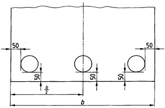 |
Key
b Strip or sheet width
Figure 1 — Position of the samples for determining the coating mass
If sampling as shown in Figure 1 is not possible because the product width is too small, only one sample
shall be taken with an area of at least 5 000 mmІ. The coating mass determined from it shall comply with
the requirements for the single spot test as specified in Table 3.
8.4.4 All the samples shall be taken and machined, if necessary, in such a way that the results of the
tests are not affected.
8.5 Test methods
8.5.1 The tensile test shall be carried out as specified in EN 10002-1 using type 2 test pieces (initial
gauge length L0 = 80 mm, width b = 20 mm) (see also 7.2.4).
8.5.2 The determination of the plastic strain ration r and the strain hardening exponent n shall be
carried out in accordance with ISO 10113 and ISO 10275.
The plastic strain ratio r and the strain hardening exponent n are determined within the strain range of 10
% to 20 %. As the determination shall be carried out in the range of homogeneous deformation, then if
the uniform elongation of the tested material is lower than 20 %, values for the upper limit of the strain
range of 15 % to 20 % can be applied.
8.5.3 The coating mass shall be determined from the difference in mass of the samples before and
after the coating has been removed chemically. In the test with specimen according to Figure 1, the
triple spot test value is the arithmetic mean of the three test results. Each individual result shall meet the
requirements of the single spot test as given in Table 3.
Other methods — e.g. non-destructive tests — may be used for continuous checks at the manufacturer's
works.
In cases of dispute, the methods described in Annex A (Z, ZA and AZ) or Annex B (AS) of this document
shall be used.
8.6 Retests
The requirements of EN 10021 shall apply. In the case of coils, the retest specimens shall be taken from
a distance of at least one lap away, but with a maximum of 20 m from the end of the coil.
9 Marking
9.1 A label shall be attached to each coil or bundle containing at least the following information:
a) name or mark of the manufacturer's works;
b) designation (consisting of 5.1b) and 5.1f) to 5.1k));
c) nominal dimensions of the product;
d) identification number;
e) order number;
f) mass of the coil or bundle.
9.2 Marking of the products by branding may be agreed at the time of enquiry and order.
10 Packing
The packing requirements for the product shall be agreed at the time of enquiry and order.
11 Storage and transportation
11.1 Moisture, in particular condensation between the sheets, laps of the coil or other adjacent parts
made of hot-dip coated flat products can lead to the formation of corrosion products. The possible types
of temporary surface protection are given in 7.6. As a precaution, the products should be transported
and stored dry and protected from moisture.
11.2 During transportation, dark spots may appear on the hot-dip coated surfaces as a result of friction.
Generally, they only impair the appearance. Friction is reduced by oiling the products. However, the
following precautionary measures should be taken: secure packing, laid flat, no local pressure spots.
12 Disputes
EN 10021 is applicable to disputes after delivery and their settlement.
Annex A
(normative)
Reference method for determination of the zinc, zinc-aluminium and
aluminium-zinc coating mass
A.1 Principle
The sample shall be at least 5 000 mmІ in area. Using a sample with a surface area of 5 000 mmІ, the loss
of mass in grams when the coating is dissolved, multiplied by 200, will represent the coating mass in grams
per square metre of the product, including both sides.
A.2 Reagent and preparation of the solution
Reagent:
- Hydrochloric acid (HCl ρ20 = 1,19 g/ml)
- Hexamethylenetetramine
Preparation of the solution:
The hydrochloric acid is diluted with deionized or distilled water in the ratio one part pure HCl to one part
water (50 % dilution). Hexamethylenetetramine is then added, stirring, in the ratio of 3,5 g per litre of dilute
hydrochloric acid solution.
This prepared solution permits the execution of numerous successive dissolutions under satisfactory
conditions of attack of the coating, both from the point of view of speed and accuracy.
A.3 Apparatus
Balance capable of weighing samples to an accuracy of 0,001 g. For the test, use a take-off device.
A.4 Procedure
The following operations are applied to each sample:
a) if necessary, degrease the sample with an organic solvent which will not attack the coating, then dry the
sample;
b) weigh the sample to an accuracy of 0,001 g;
c) place the sample in the hydrochloric acid solution with hexamethylenetetramine inhibitor at ambient
temperature (20 °C to 25 °C). Leave the sample immersed in the solution until the release of hydrogen
ceases or only a few bubbles are released;
d) after the attack, the sample is washed and brushed under running water, dried with a cloth and then by
heating to around 100 °C and cooled or dried by blowing with warm air;
e) weigh the sample again to an accuracy of 0,001 g;
f) determine the difference between the mass of the coated sample and that of the sample without its
coating. This difference, calculated in grams, represents the mass m of the coating.
Annex B
(normative)
Reference method for determination of the aluminium-silicon coating mass
B.1 Principle
The method described below is used for determining the coating mass of hot-dip aluminium-silicon coated flat
products. The samples are weighed before and after the coating is removed.
B.2 Reagents
- Hydrochloric acid (HCl ρ20 = 1,19 g/ml).
- Sodium hydroxide solution with 20 % concentration made by dissolving 20 g sodium hydroxide in 80 ml of
water.
B.3 Procedure
B.3.1 Samples
The samples are taken from the product in accordance with 8.4.4.
The samples shall be clean. If necessary, they are to be washed firstly with suitable solvents, which will not attack the
coating, then secondly in alcohol. Finally, they are thoroughly dried.
B.3.2 Method
After washing as specified in B.3.1, the samples are weighed to an accuracy of 0,001g and then placed in the hot
sodium hydroxide solution until the reaction ceases. Then the test samples are taken out of this solution, rubbed under
water, roughly dried off with a cloth and placed in cold hydrochloric acid for 2 s to 3 s.
The samples are then rinsed under water and again immersed in the sodium hydroxide solution until no further
reaction can be established. This process is to be repeated until no reaction is visible when the sample is dipped into
the sodium hydroxide solution. The samples are then washed, dried and re-weighed (accuracy 0,001g).
B.4 Evaluation
The coating mass in grams per square metre of the product (on both sides) is obtained from the formula:
m (m 1 0 10 )Ч − 6
A
where
m0 is the mass of the sample before the coating is stripped off, in grams;
m1 is the mass of the sample after the coating has been removed, in grams;
A is the area of the sample used in square millimetre.
Annex C
(normative)
Method for determination of the mass of the Al-Fe-Si alloy layer
C.1 Principle
The method described below is used for determining the mass of the alloy layer on samples of hot-dip aluminium-
silicon coated flat products. Firstly, the so-called non-alloy layer and secondly the alloy layer are removed, according to
the method in Annex B. The method is based on the reaction of tin (II) chloride solution with aluminium to form metallic
tin (sponge); this solution does not react with the alloy or with the iron base material. The samples are weighted before
and after removal of the alloy layer.
C.2 Reagents
C.2.1 Tin (II) chloride solution
C.2.1.1 To produce the stock solution, 1 000g SnCl2 x H2O are dissolved in 500 ml of diluted hydrochloric acid (1:1).
Make up to 1 000 ml adding 5 g to 10 g metallic tin. Heat until the solution is clear.
C.2.1.2 To produce the test solution, 20 ml of stock solution are added to 200 ml H2O immediately prior to use.
C.3 Procedure
C.3.1 Removal of the non-alloy layer
The samples, taken in accordance with 8.4.4 are cleaned with petroleum ether and immersed in 200 ml of test solution
(see C.2.1.2) until the reaction ceases.
Once the test samples have been removed from the solution, the sponge tin is scraped off with a small spatula. The
process is repeated until no further reaction takes place. The samples are then washed and dried.
C.3.2 Determination of alloy layer
The test samples prepared in accordance with C.3.1 are treated as described in B.3.2.
C.4 Evaluation
The mass of the alloy layer is calculated using the formula in B.4, from the difference in mass of the samples before
and after the test.